

LCD 16×2 Pin Configuration and Its Working
Blaze Display Technology Co., Ltd. | Updated: Nov 27, 2018
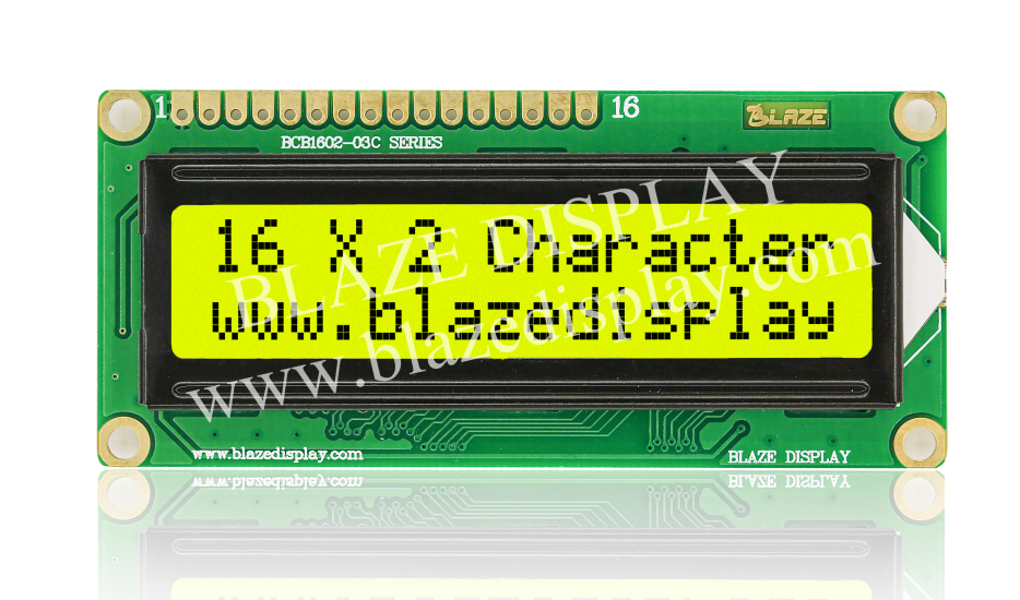
What is the LCD 16×2?
LCD 16*2 is a type of liquid crystal display(LCD)that an display up to 16 characters per line and 2 lines. These displays are widely used in a variety of applications, such as displaying text or data in electronic projects. The LCD is operated through a built-in controller that can understand and execute a series of commands. These commands allow for functions like setting the cursor position clearing the display, and controlling the on/off state of the display. The LCD 16*2 is a widely used device in electronic projects, such as showing text or data.
LCD 16*2 Pin Diagram
· Pin1 (Ground/Source Pin): This is a GND pin of display, used to connect the GND terminal of the microcontroller unit or power source.
· Pin2 (VCC/Source Pin): This is the voltage supply pin of the display, used to connect the supply pin of the power source.
· Pin3 (V0/VEE/Control Pin): This pin regulates the difference of the display, used to connect a changeable POT that can supply 0 to 5V.
· Pin4 (Register Select/Control Pin): This pin toggles among command or data register, used to connect a microcontroller unit pin and obtains either 0 or 1(0 = data mode, and 1 = command mode).
· Pin5 (Read/Write/Control Pin): This pin toggles the display among the read or writes operation, and it is connected to a microcontroller unit pin to get either 0 or 1 (0 = Write Operation, and 1 = Read Operation).
· Pin 6 (Enable/Control Pin): This pin should be held high to execute Read/Write process, and it is connected to the microcontroller unit & constantly held high.
· Pins 7-14 (Data Pins): These pins are used to send data to the display. These pins are connected in two-wire modes like 4-wire mode and 8-wire mode. In 4-wire mode, only four pins are connected to the microcontroller unit like 0 to 3, whereas in 8-wire mode, 8-pins are connected to microcontroller unit like 0 to 7.
· Pin15 (+ve pin of the LED): This pin is connected to +5V
· Pin 16 (-ve pin of the LED): This pin is connected to GND.
Features of LCD 16x2
The LCD 16*2 features a screen with the capability to display up to 16 characters per line and 2 lines. This makes it well-suited for showcasing concise messages or presenting data in a compact format.
· Built-in controller
· Low power consumption
· Wide Operating Temperature range
· Easy to interface
· Variety of commands
· High visibility
Registers of LCD
A 16×2 LCD has two registers like data register and command register. The RS (register select) is mainly used to change from one register to another. When the register set is ‘0’, then it is known as command register. Similarly, when the register set is ‘1’, then it is known as data register.
(1) Command Register
The main function of the command register is to store the instructions of command which are given to the display. So that predefined tasks can be performed such as clearing the display, initializing, set the cursor place, and display control. Here commands processing can occur within the register.
(2) Data Register
The main function of the data register is to store the information which is to be exhibited on the LCD screen. Here, the ASCII value of the character is the information which is to be exhibited on the screen of LCD. Whenever we send the information to LCD, it transmits to the data register, and then the process will be starting there. When register set =1, then the data register will be selected.
16×2 LCD Commands
The commands of LCD 16X2 include the following.
· For Hex Code-01, the LCD command will be the clear LCD screen
· For Hex Code-02, the LCD command will be returning home
· For Hex Code-04, the LCD command will be decrement cursor
· For Hex Code-06, the LCD command will be Increment cursor
· For Hex Code-05, the LCD command will be Shift display right
· For Hex Code-07, the LCD command will be Shift display left
· For Hex Code-08, the LCD command will be Display off, cursor off
· For Hex Code-0A, the LCD command will be cursor on and display off
· For Hex Code-0C, the LCD command will be cursor off, display on
· For Hex Code-0E, the LCD command will be cursor blinking, Display on
· For Hex Code-0F, the LCD command will be cursor blinking, Display on
· For Hex Code-10, the LCD command will be Shift cursor position to left
· For Hex Code-14, the LCD command will be Shift cursor position to the right
· For Hex Code-18, the LCD command will be Shift the entire display to the left
· For Hex Code-1C, the LCD command will be Shift the entire display to the right
· For Hex Code-80, the LCD command will be Force cursor to the beginning ( 1st line)
· For Hex Code-C0, the LCD command will be Force cursor to the beginning ( 2nd line)
· For Hex Code-38, the LCD command will be 2 lines and 5×7 matrix
The LCD 16*2 display is a versatile and widely used component in the world of electronics. We expolored its various aspects, including the pin diagram,registers, commands,etc. The LCD 16*2 offers a compact powerful interface for displaying information, making it a favorite choice for projects requiring visual output . whether you are a beginner or an experienced hobbyist ,mastering the LCD 16*2 can enhance your electronics skills and bring your projects to life.